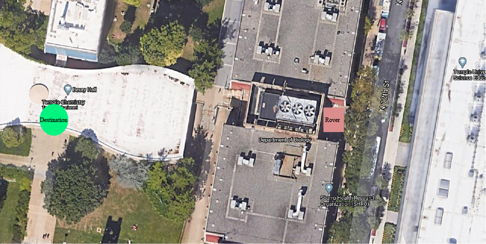
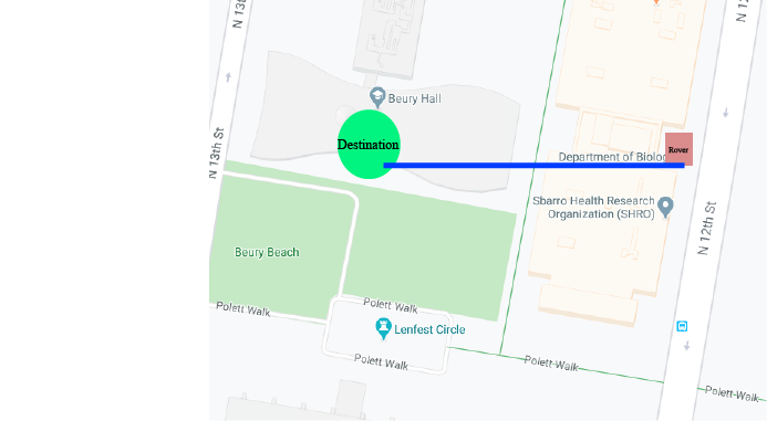
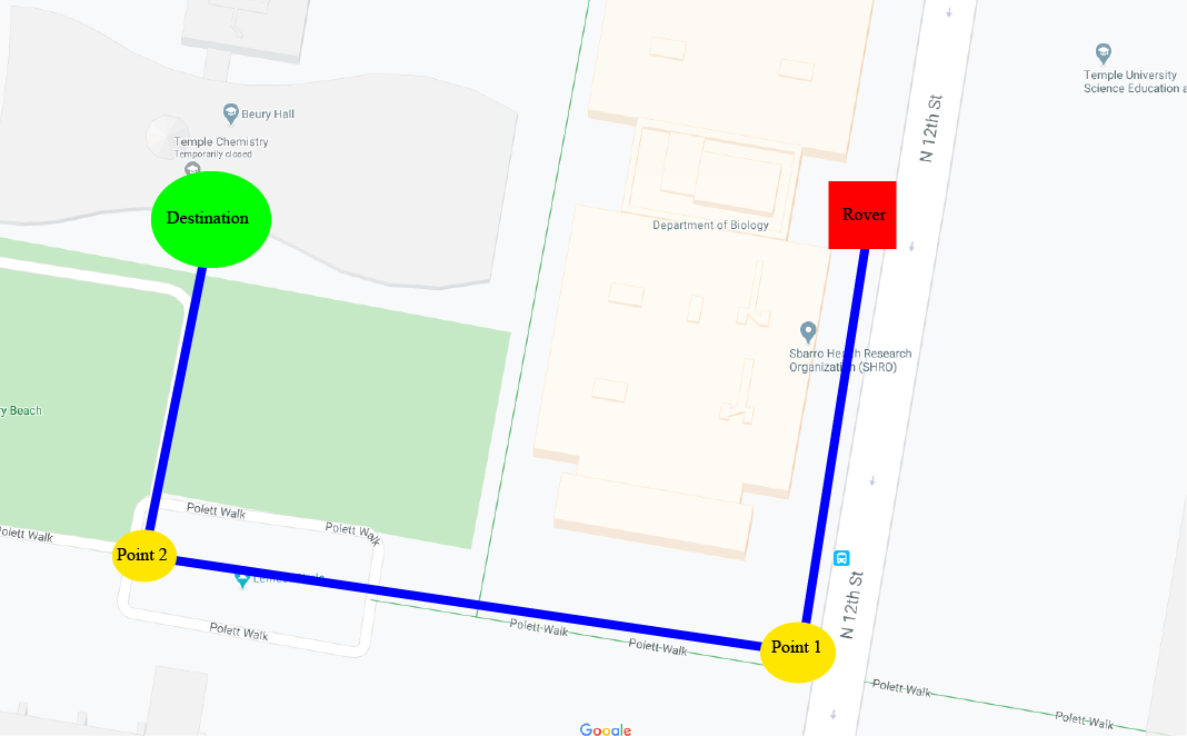
Destination Visual
A destination is given to the Rover, and then it calculates a striaght line towards that destination.
An open source project to recreate a miniature NASA Marss Rover
Funded by NASA PSGC
An IMU is used to follow the straight line. It calculates the Rover's direction, movement, and orientation to get to the destination.
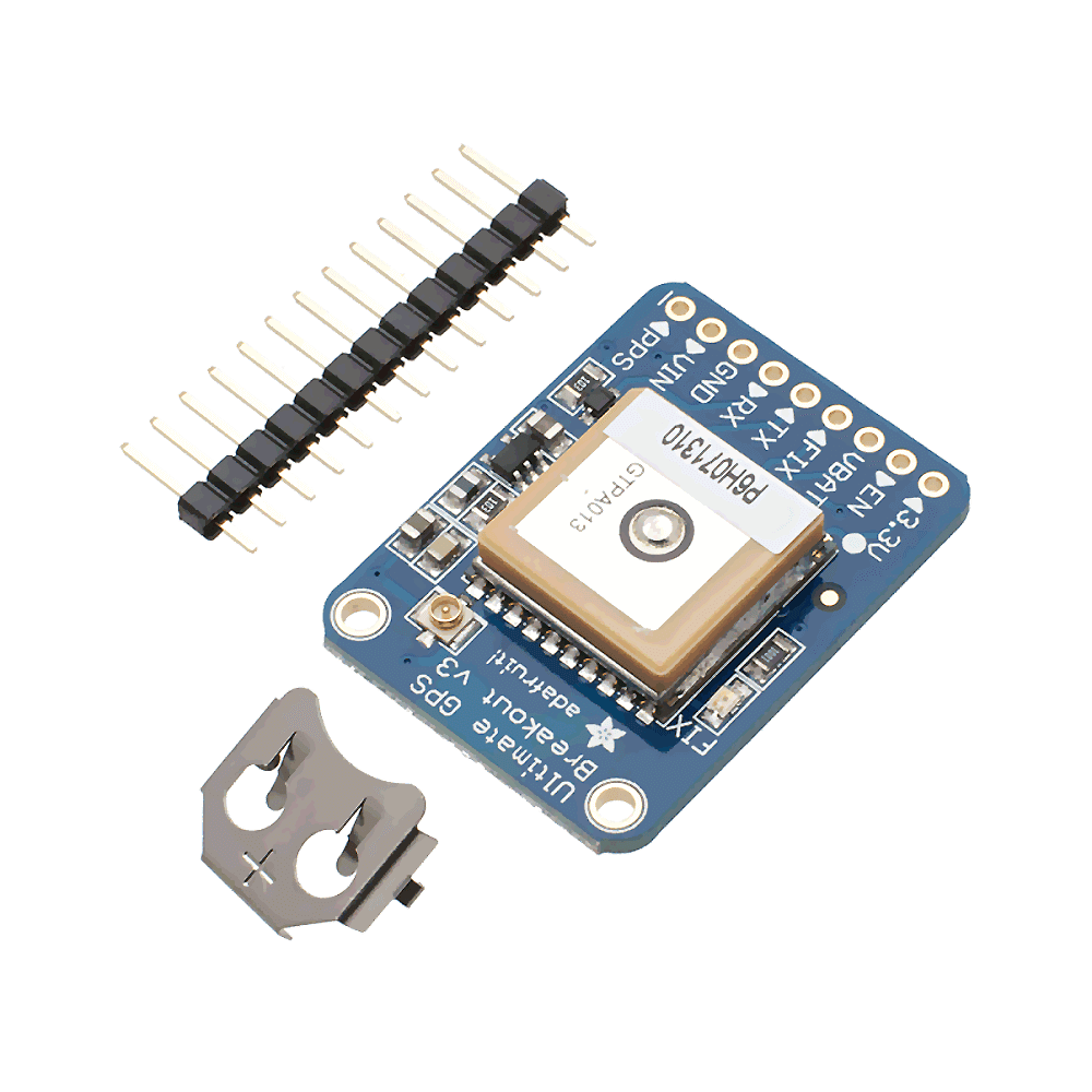
The GPS keeps track of where the Rover is at all times.
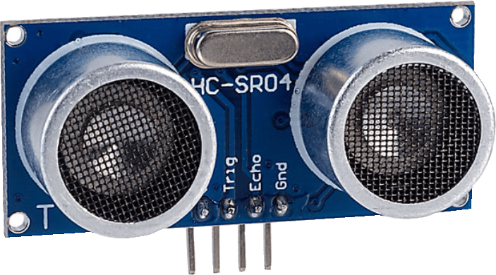
Range 190cm, Field of View 30 degrees. Method: Ultrasonic
An Ultrasound is used to detect objects. Ultrasounds have an emitter and a receiver. The sound emitted bounces off of a nearby object. The receiver detects this sound. Distance is found by measuring the time it takes for the receiver to receive the emitted sound.
We find the bearing and check if the bearing equals the heading. If correct continue forwards, else spin.
If an obstacle is encountered avoid obstacle and then proceed to tracking algorithm.
Benefits:
Head straight to our destination!

We find the bearing and check if the bearing equals the heading. If correct continue forwards, else spin.
If an obstacle is encountered avoid obstacle and then proceed to tracking algorithm.
Benefits:

In order to avoid an obstacle it must be detected. There are various sensors used for object detection.
Let's describe a few of them:
Sensors
We have chosen to focus on LIDAR and Ultrasound. While the others are being developed more.
Range 190cm, Field of View 30 degrees. Method: Ultrasonic
Ultrasounds have an emitter and a receiver. The sound emitted bounces off of a nearby object. The receiver detects this sound. Distance is found by measuring the time it takes for the receiver to receive the emitted sound.
Due to ultrasound only giving back a scalar value, exact position of the object detected can not be found. Instead, the futher the range, the less exact the angle.


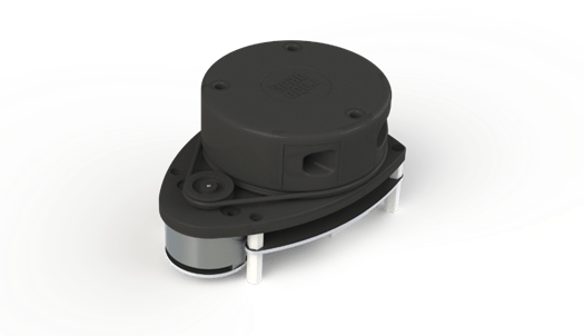
Range 4-5 meters, angle and distance, Method: Light
LIDAR sends a laser multiple times per second. It rotates at a certain rate, allowing for 360 detections.
In order to rotate in 3D we must first define a class to handle such. We will use vectors. For 3D rotation three angles, the yaw, pitch, and roll, are used. We can calculate these by describing rotations as a matrix. on each axis.


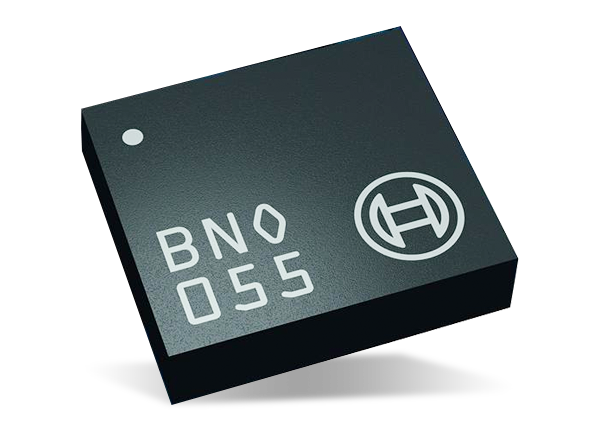
Gyroscopes calculate angular velocity. It can calculate the angular velocity of all three axes. Gyroscopes uses a spinning gimbal to lock each axis in place. When the axes are displace, this is calculated as a force. The force can be calculated mathematically via the cross product.


We can instead rotate via outter products. This method uses the bivector, which represents the plane produced by taking the outter product. This is similar to representing rotations via the cross product, or the gyrscope.
Bivectors contain components just like a vector, but in terms of a plane and not a line. Through reflections, a bivector can be split into a component within a plane and outside the plane. These two components can be used to calculate the rotation on the three axes. This method is known as a Rotor.
When extended into 3D the most commonly used Rotor is known as the Quaternion. Quaternions are a special case of a Rotor, where i, j, k represents the rotation. Quaternions are special because they use complex numbers to represent rotations.

Even with gyrscope and quaternions it is still not accurate enough to calulcate angular positioning.
Gyrscopes get angular velocity. By taking the integral you can derive the position, but it comes with a fair degree of error. Magnetometer gives exact angular position, based on absolute world coordinates (true magnetic north), instead of relative coordinates.

However, due to magnetometer calculating a weak force, Earth's magnetic field, it has a fair degree of error as well.
Many devices can produce a local magnetic field, and thus cause the magnetometer to read falsely. In standard testing, this is usually an error of 10-7 degrees.
Accelerometers are the perfect device. By measuring force from acceleration. It can calculate not just orientation, but also rotation.
These can be derived by double integrating the accelerometer. In order for this to be achieve gravity must be removed.
Accelerometers will experience a force of 9.8ms^2 due to gravity. However, as the object rotates this force is distributed along all three axes. In order to remove this force we must subtract it, or find its inverse. This can be done by multiplying with our rotation matrix and solving.


However, the yaw is still missing. By definition, an accelerometer cannot properly calculate the yaw angle. We must combine all three devices in order to get accurate orientation....
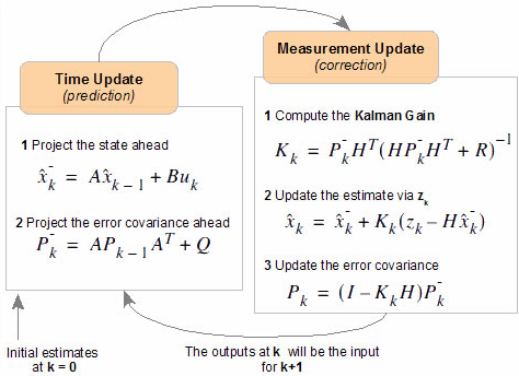
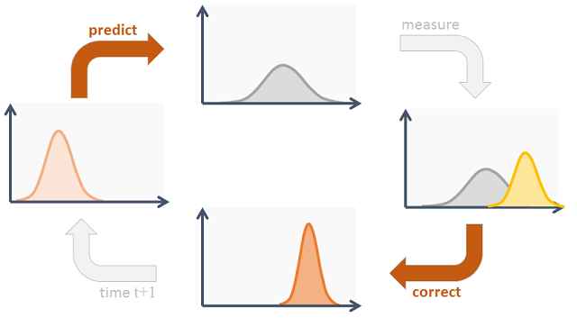
Being computer science, we can use a technique commonly found in machine learning and statistics. That is mathematical filters. One such filter is the Kalman Filter. We can use the data from all three sensors and try to predict the next value based on the previous values. A brief view of the Kalman Filter is as follows
Accuracy: 3-10 meters, update per second, use case: global coordinates.
Finding position is the second challenge. GPS is an excellent device for tracking position over a wide field. This does not mean GPS is perfect. GPS gives only an estimated positioning.
The bearing is the angle at which the rover needs to turn in order to reach a certain destination. This can be represented as a vector. With an angle and distance, the rover can travel the imaginary line.
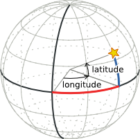
However, earth is a sphere, thus this requires a method to convert the coordinates in terms of distance, and angles. For this we use spherical coordinates.
Sperhical coordiantes is a coordinate system for 3D which uses the radial distance and angles (theta, phi) to produce a vector. The bearing can then be calculate by the same principles, using spherical trigonometry.
